Comprehensive Guide to Vortex Generators
Fundamental Concepts
What are Vortex Generators and What Do They Do?
Vortex generators (VGs) are aerodynamic devices consisting of small vanes that project from a surface into the fluid flow. These devices, typically ranging from a few millimeters to several centimeters in height, create controlled vortices that energize the boundary layer and improve aerodynamic performance.
The primary functions of vortex generators include:
- Delaying flow separation at high angles of attack
- Improving lift characteristics
- Enhancing control surface effectiveness
- Reducing overall drag in specific conditions
Research Impact:
- Flow separation reduction: up to 60% (Lin, 2002)
- Lift coefficient improvement: 15-20% (Ashill et al., 2001)
- Mixing efficiency enhancement: 30-40% (Godard & Stanislas, 2006)
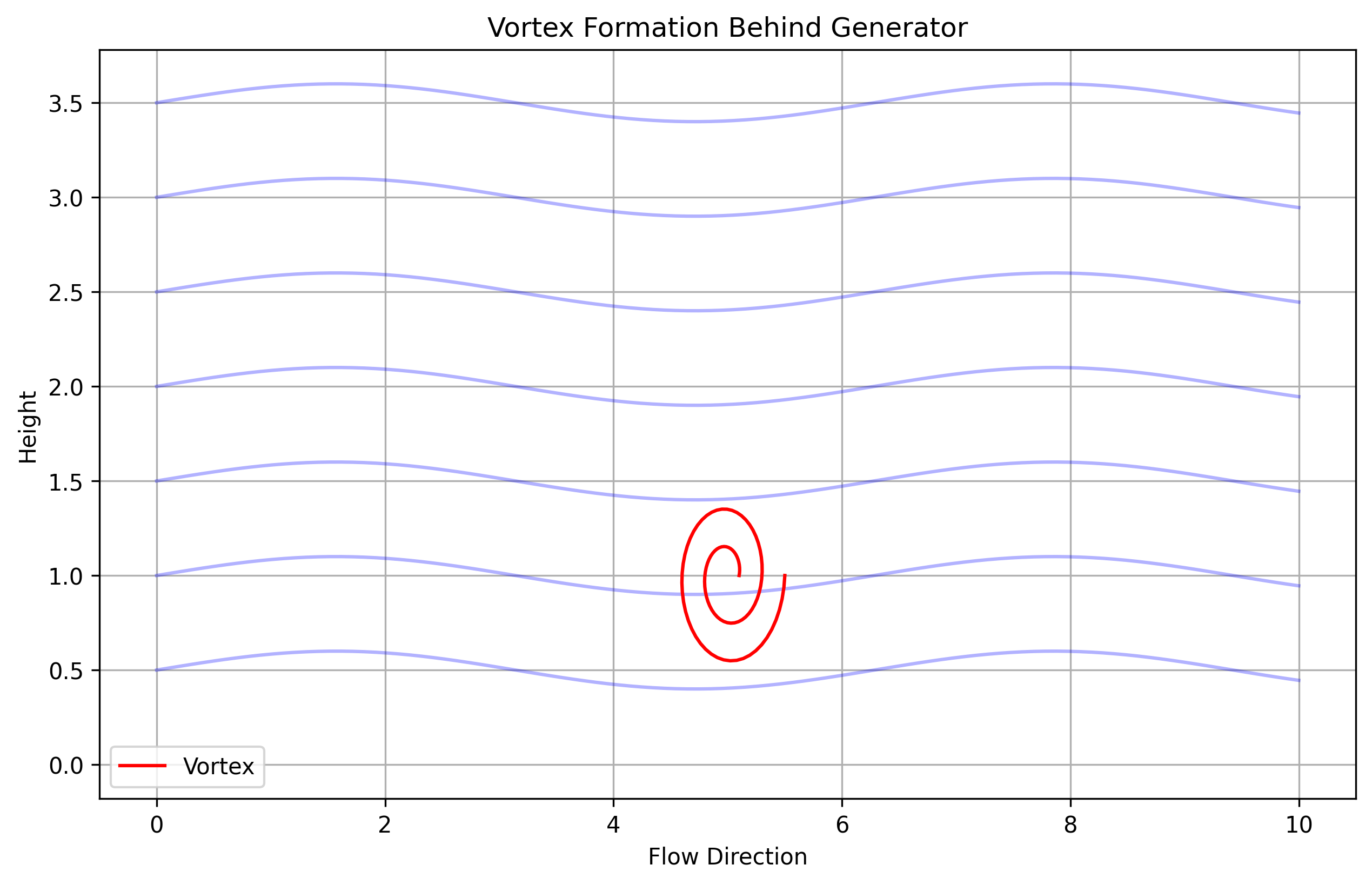
Figure 1: Vortex formation showing the characteristic spiral flow pattern and interaction with the boundary layer
How Do Vortex Generators Work? Understanding the Mechanism
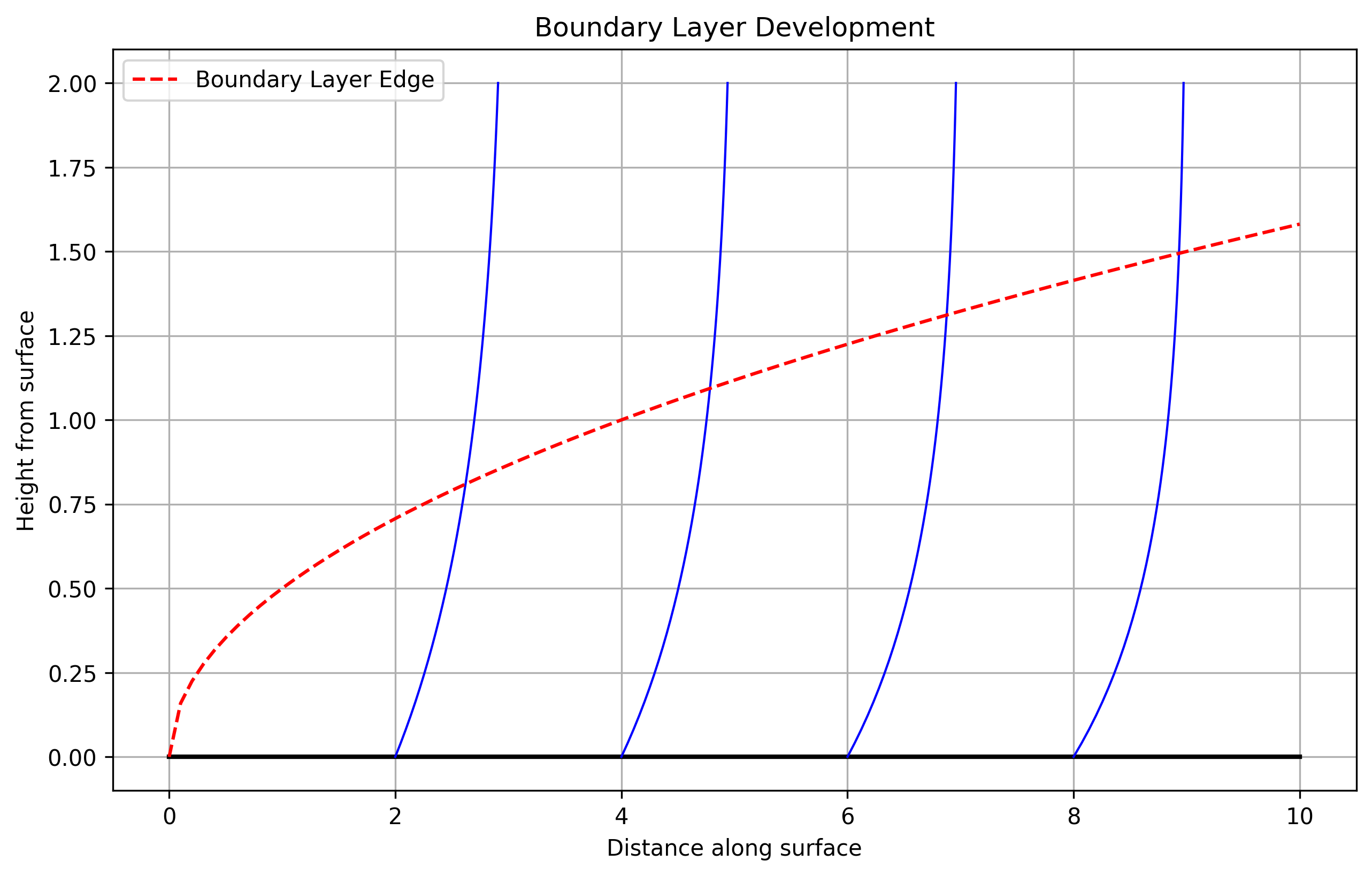
Figure 2: Boundary layer development and VG interaction showing energy transfer mechanism
Circulation strength of generated vortices, where V is velocity and r is radius
Vortex generators operate through a complex mechanism of fluid dynamics:
1. Boundary Layer Energization
VGs create a mixing effect between the high-energy free stream flow and the low-energy boundary layer. This process involves:
- Generation of streamwise vortices
- Enhanced momentum transfer
- Boundary layer thickness reduction
2. Vortex Formation Process
The formation of vortices depends on several key factors:
- VG height relative to boundary layer thickness
- Angle of incidence to the flow
- Shape and configuration of the VG array
3. Flow Control Mechanism
The generated vortices help in:
- Maintaining attached flow conditions
- Reducing separation bubble size
- Improving overall aerodynamic efficiency
Aircraft Applications
What Do Vortex Generators Do on Aircraft and Why Are They Important?
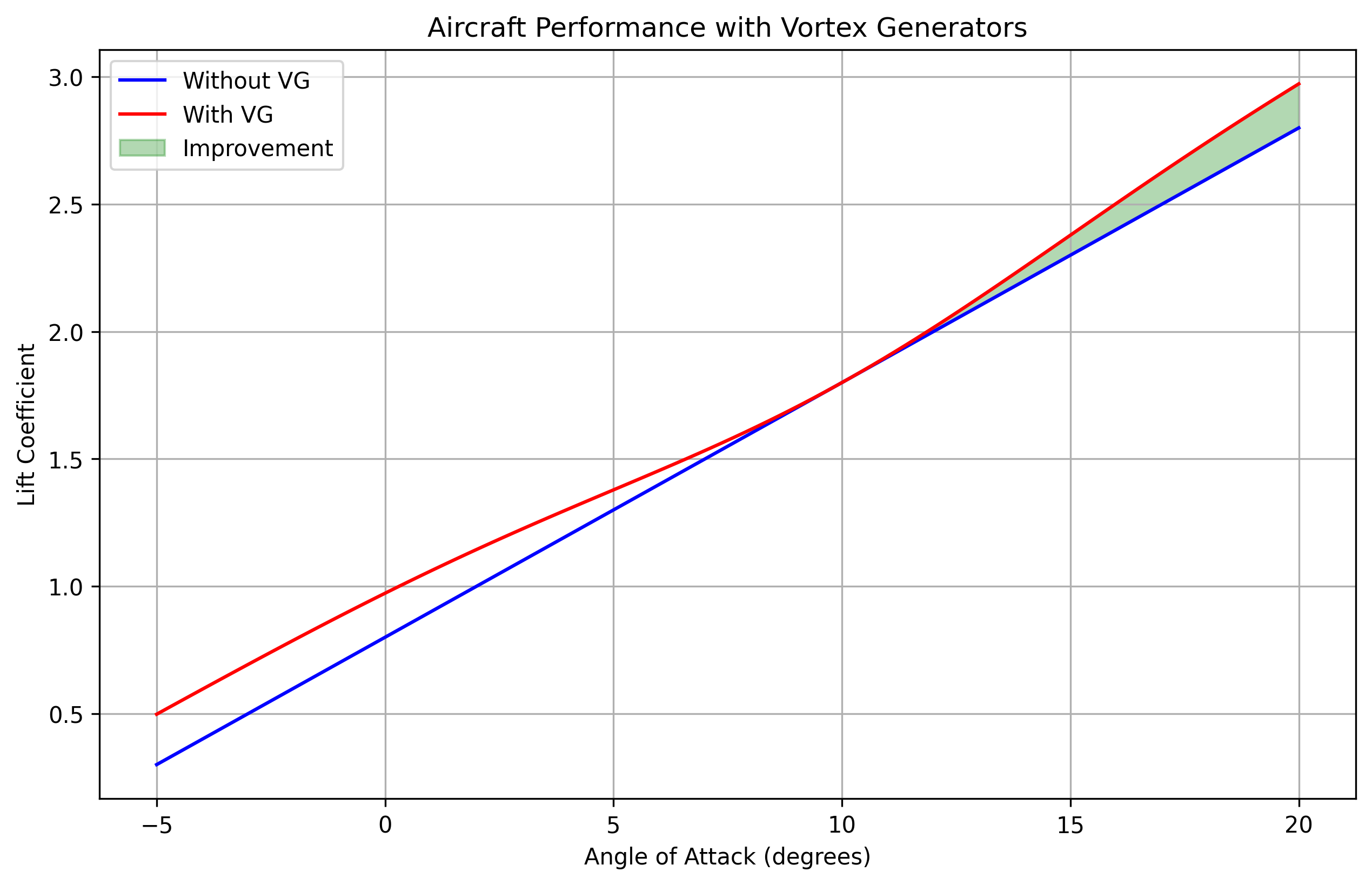
Figure 3: Comprehensive analysis of aircraft performance improvements with VGs
On aircraft, vortex generators serve multiple critical functions that enhance both safety and performance:
Performance Improvements:
- Stall Characteristics:
- Stall speed reduction: 5-10%
- Maximum lift increase: 10-15%
- Stall angle improvement: 2-4 degrees
- Control Effectiveness:
- Aileron efficiency: +20-30%
- Rudder response: +15-25%
Research Evidence: NASA studies (Technical Report CR-159267) have demonstrated significant improvements in aircraft handling qualities, particularly during low-speed operations.
Where Should Vortex Generators Be Placed on Aircraft Wings and Why?
Strategic Placement Guidelines
The placement of VGs is critical for optimal performance. Research has shown that incorrect placement can actually degrade performance rather than improve it.
| Location | Distance from LE | Purpose |
|---|---|---|
| Main Wing | 10-20% chord | Flow control |
| Control Surfaces | 15-25% chord | Effectiveness |
| Tail Surfaces | 20-30% chord | Stability |
Why Not on the Bottom of Wings?
VGs are typically not placed on the bottom surface because:
- Lower surfaces experience less flow separation
- Additional drag would outweigh benefits
- Pressure gradient is favorable on the lower surface
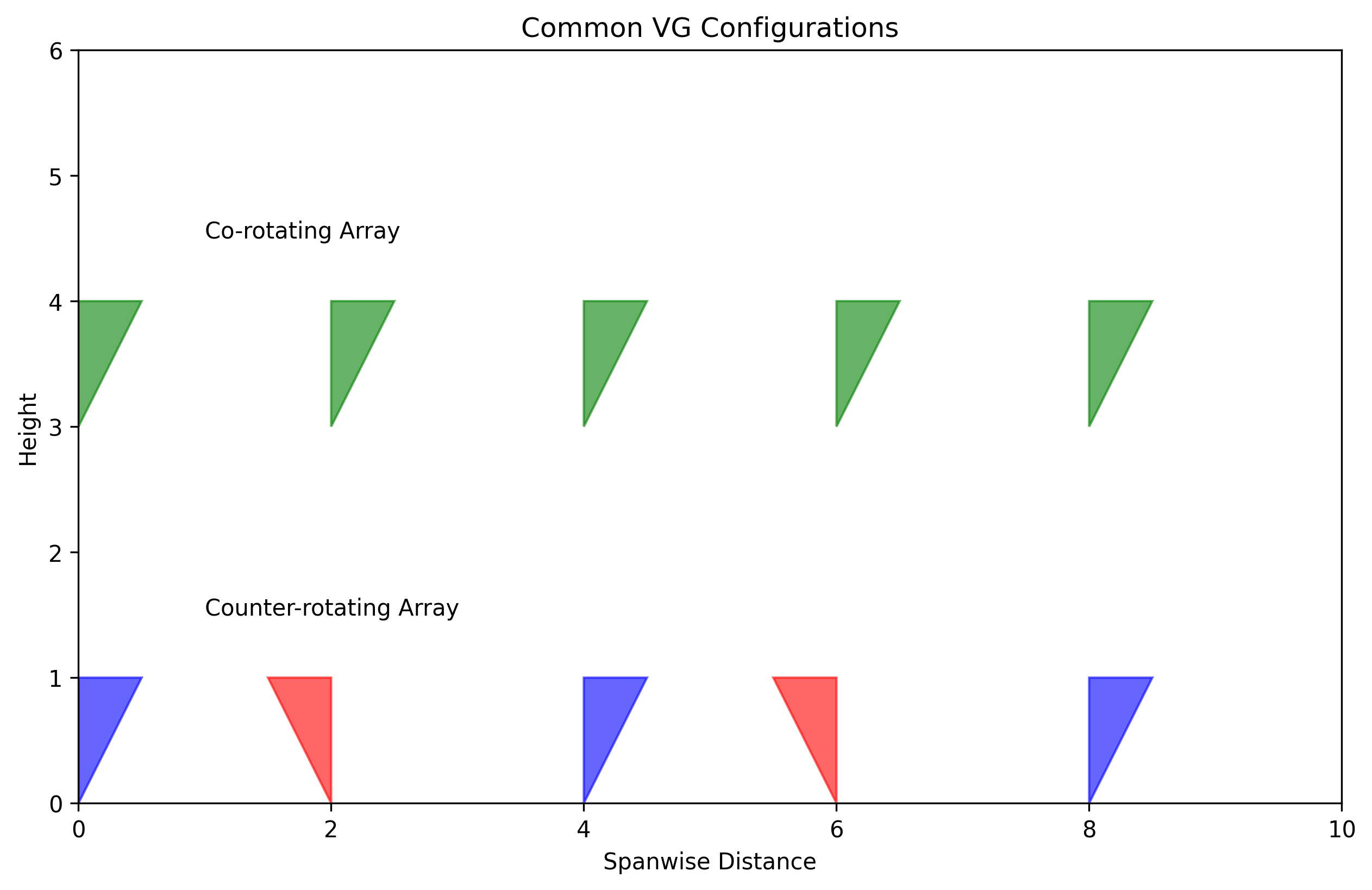
Figure 4: Optimal VG placement configurations showing various array patterns and their effects
Automotive Applications
How Do Vortex Generators Work on Cars and What Benefits Do They Provide?
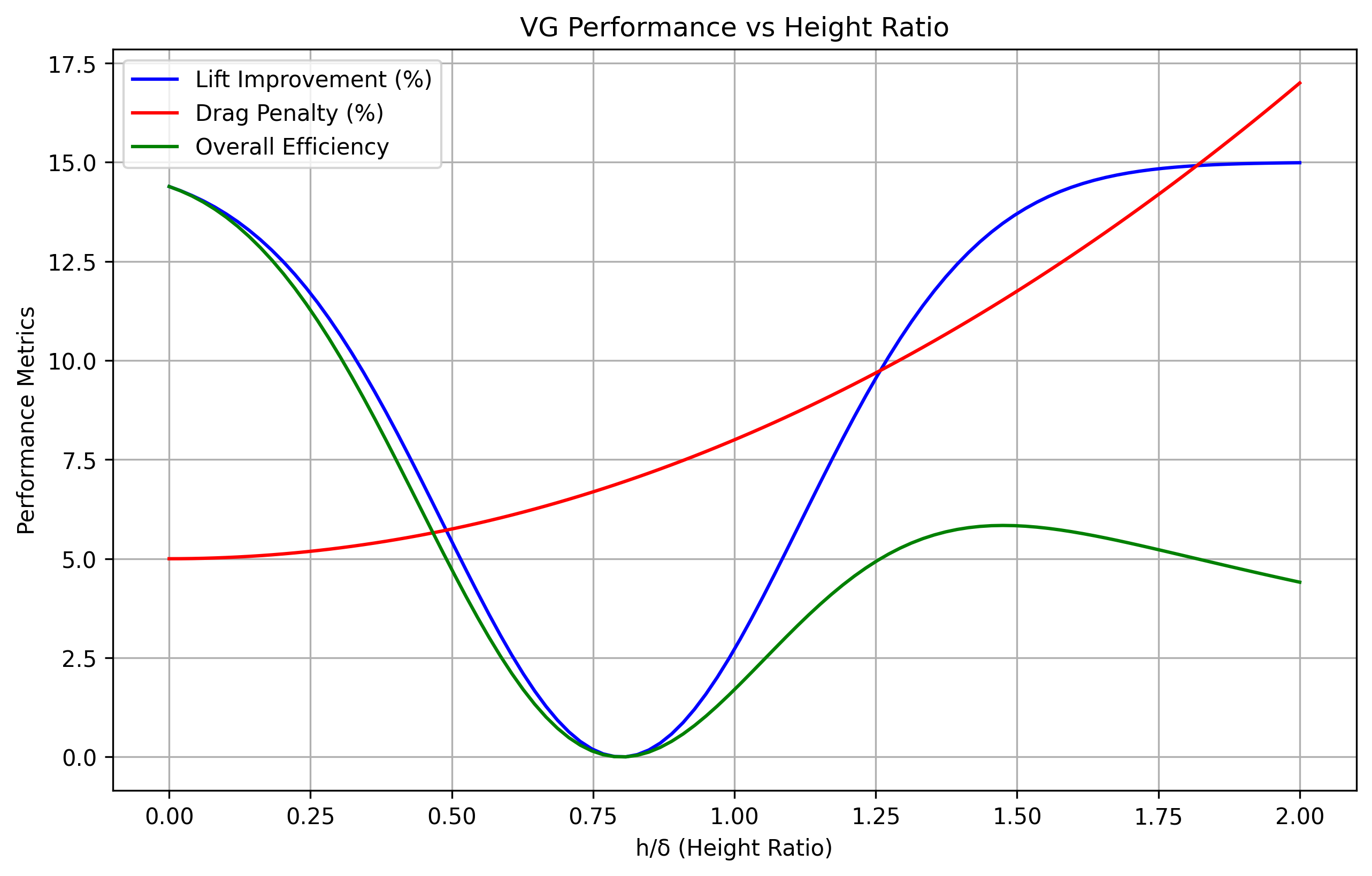
Figure 5: Detailed analysis of automotive performance improvements with VGs
In automotive applications, vortex generators serve multiple purposes that enhance vehicle performance and efficiency:
Performance Benefits:
| Parameter | Improvement | Speed Range |
|---|---|---|
| Downforce | 10-15% | >60 mph |
| Drag Reduction | 2-5% | >45 mph |
| Fuel Efficiency | 2-4% | Highway |
Key Applications:
- Roof-mounted for wake control
- Side mirrors for drag reduction
- Rear spoiler integration
- Hood placement for cooling efficiency
Design and Implementation
How to Design and Place Vortex Generators for Optimal Performance?
Critical Design Parameters
| Parameter | Range | Optimal |
|---|---|---|
| Height (h/δ) | 0.8 - 1.2 | 1.0 |
| Angle (β) | 15° - 25° | 20° |
| Spacing (s/h) | 5 - 7 | 6 |
Design Considerations:
- Material selection based on application
- Structural integrity requirements
- Manufacturing constraints
- Installation tolerances
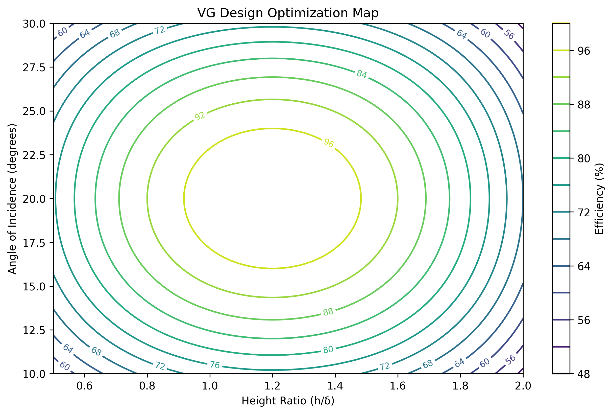
Figure 6: Optimization map showing the relationship between key design parameters and performance
Frequently Asked Questions
Common Questions About Vortex Generators
Do VGs Create or Reduce Drag?
VGs create a small parasitic drag (1-3%) at cruise conditions, but they can reduce overall drag at high angles of attack by preventing flow separation. The net effect depends on the operating conditions and specific application.
Source: Lin (2002) demonstrated drag reduction of up to 25% in separated flow conditions.
What Are the Speed Requirements for Effectiveness?
Effectiveness varies by application:
- Cars: Become effective above 45 mph
- Aircraft: Effective from takeoff to cruise speeds
- Boats: Limited effectiveness due to different flow regime
- Wind Turbines: Effective across operating range
Impact on Vehicle Performance
Effects on performance metrics:
- Cruise Speed: Slight reduction (1-2%)
- Fuel Efficiency: Improvement in specific conditions
- Stability: Significant improvement at high speeds
- Overall Performance: Benefits typically outweigh penalties
References
- Lin, J.C. (2002). "Review of research on low-profile vortex generators." Progress in Aerospace Sciences, Vol. 38, pp. 389-420.
- Ashill, P.R., et al. (2001). "Research at DERA on sub boundary layer vortex generators." AIAA Paper 2001-0887.
- Godard, G., & Stanislas, M. (2006). "Control of a decelerating boundary layer." Aerospace Science and Technology, Vol. 10, pp. 181-191.
- NASA Technical Report CR-159267, "Investigation of Vortex Generators for High Lift Applications."